Earthing and Grounding System Part 1 [General Knowledge & in LV System: Residentials]
Ever try to unplug an electrical appliance but end up getting shocked? Even though the cable is not peeled off and everything looks fine. Well maybe because of this one.

Our home systems are usually single-phase, and as we see in the other country's plugs, there are 2 lines, which are phase and neutral (positive and negative). But in the socket-outlet hole, especially in India and China, there is usually a third line, called the grounding line.
These third points are supposed to be connected to the electrical panel box, and then the electrical panel is earthed to the ground through the grounding electrodes found in the earth pit (grounding control basin), constructed like a septic tank.
if the electric equipment didn't grounded, then your body will being the conductors/electrodes.
1. The earth acts as a static reference (meaning it has a potential of ~zero volts) on the connected system. Thus, any conductor connected to the grounding electrode will also have the same potential value (~0 V). So there will be no such thing as a shock due to the potential difference.
2. Conductors, grounding electrodes, and electrical equipment play a role in providing a path for electricity to flow.
b. Strip
One benefit of strip earthing is its exceptional corrosion resistance. It makes it possible for current to flow from electrical equipment to the ground efficiently via a low-resistance metallic strip.
The 6 mm-diameter strips used for strip earthing are hot-dip galvanized. After that, they are buried 0.5 meters below the surface in horizontal trenches.

c. Plate
This kind of earth electrode guarantees endurance, affordability, and low impedance. It is built in several salt layers.

In addition to using PE conductors, there are other ways to perform Protective Earthing, namely using Overcurrent or Earth Leakage Current Protective Device (devais leakage current to the ground) which can isolate the faulted part through the identification of time duration and touch voltage on a system. If both methods are used, the PE conductor must be able to carry the faster fault current before the ELCB trips (ELCB as a backup device).
According to IEC 60364 (Electrical Installations in Buildings), Low voltage (LV) distribution systems can be identified according to their grounding system. The classification is based on the position of the grounding conductor and its neutral connection. To identify the grounding system, there are 2-4 letters that need to be understood as its identity:
1. The first letter indicates the position of the Neutral part of the grounded Phase conductor in Grid (Transformer).
T (Neutral is connected directly to the Earth, from the word: Terra (French: Earth)
I (Neutral is isolated from the Earth, from the word Insulatum (Latin: Separated)
2. The second letter indicates how the panel part of the installation (on the load/switchboard side) is grounded in building area.
T (Connected directly to the Earth, from the word: Terra (French: Earth)
N (Neutral, Connects directly to the Neutral Node)
3. The third and fourth letters indicate the condition of the neutral conductor and the protection conductor (PE Conductor).
C (Combined, Combination)
S (Separated, Separate)
There are 5 grounding configurations as illustrated below.
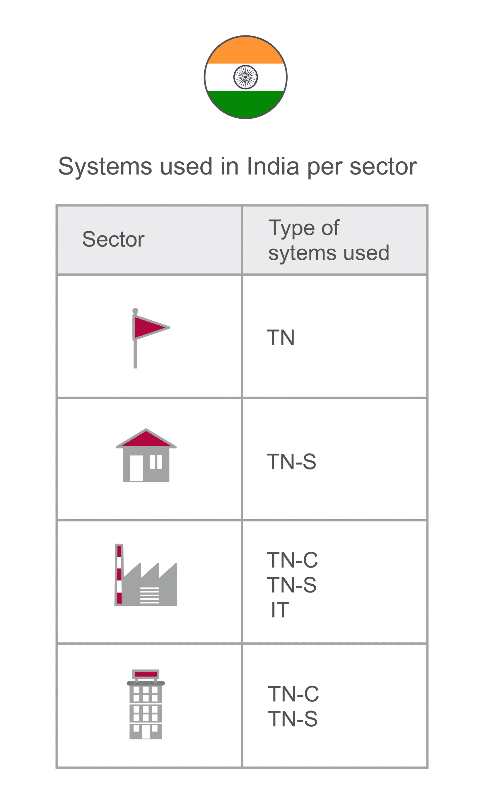
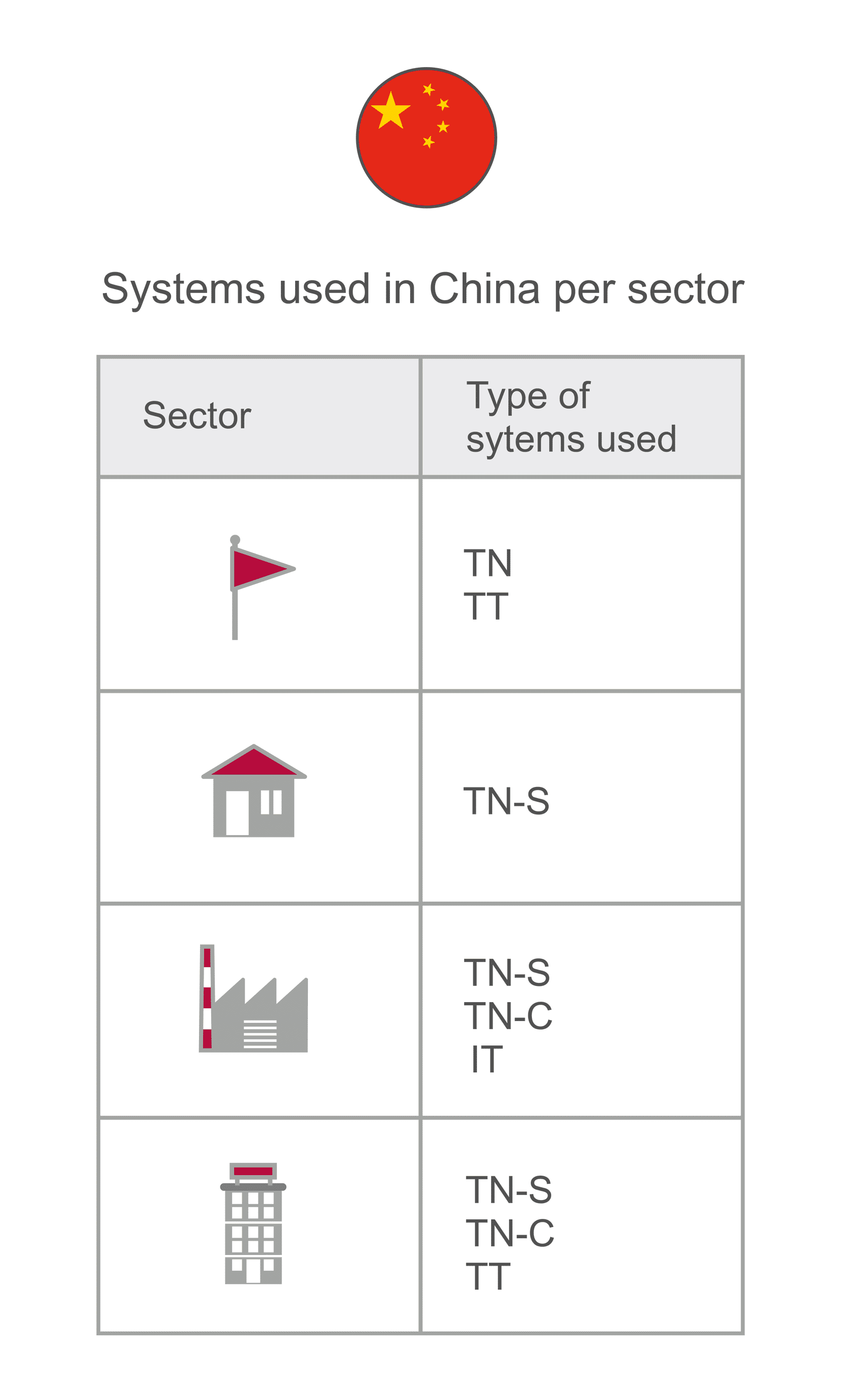
Different grounding type in India and China. From above to below: most poppular, residential, industrial, service systems.


IT grounding system with 230 V phase-to-neutral voltage is widely used in Norway.


The bad grounding systems.
Variation of Plug by Country
Our home systems are usually single-phase, and as we see in the other country's plugs, there are 2 lines, which are phase and neutral (positive and negative). But in the socket-outlet hole, especially in India and China, there is usually a third line, called the grounding line.
These third points are supposed to be connected to the electrical panel box, and then the electrical panel is earthed to the ground through the grounding electrodes found in the earth pit (grounding control basin), constructed like a septic tank.
What Earth Can Do?
Earth have a feature of the lowest resistance value, ideally it have zero ohms resistance. Earth in Grounding system will act as the zero reference so that it could neutralize charge of current from some of disturbances, such as short circuit fault, residual fault, lightning strike, also noise, and electro-mechanical interference (EMI).Component of Grounding Systems
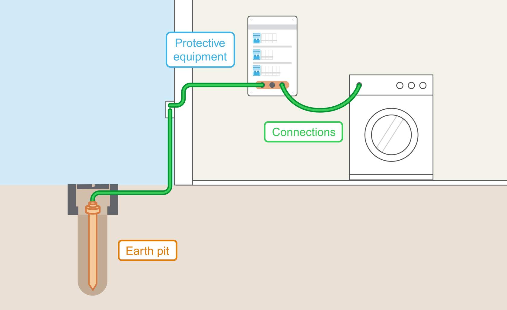
- Earth pit / electrode = conductor that digged in the ground with the special soil type (must less than 5 ohm) inside of the construction. It designed to give the electric fault the path to ground. The minimum resistance would make the current flowing easily.
- Protective equipment in panel box = such as Residual Current Circuit Breaker (RCCB) and Residual Current Breaker Overload (RCBO). The Panel Box also have teriminal for each cable.
- Connections = the proper electrical plug and the green cable path in various electric machine include here.
if the electric equipment didn't grounded, then your body will being the conductors/electrodes.
- The grounding system is a conductor system (which means, it is a good conductor of electricity and made of metal, such as copper and LV cables) that connects electrical equipment and installations (usually in electrical panels) with the earth (so connected, and must being connected to the earth) so that it secures humans, equipment, and the environment from the danger of electric current interference or stored charge.
- The grounding of electrical installations is usually done by planting electrode rod/pipe/plate in the ground and connecting these electrodes to the installation using conductors (cables).
- Every grounding system has pros and downsides, and the choice is influenced by things like the installation type, regional regulations, and particular safety needs.
Assumptions of Grounding System
There are two assumptions that can be made about the grounding system:1. The earth acts as a static reference (meaning it has a potential of ~zero volts) on the connected system. Thus, any conductor connected to the grounding electrode will also have the same potential value (~0 V). So there will be no such thing as a shock due to the potential difference.
2. Conductors, grounding electrodes, and electrical equipment play a role in providing a path for electricity to flow.
Then what is the difference between Earthing and Grounding?
Earthing = from the panel (to the ground),Bonding = connected between components,
Grounding = to the panel (from the component).
But actually in general it is equated, aka Earthing = Grounding.
There are several components of the grounding system:
Components of Grounding System
There are several components of the grounding system:
1. PE Conductor / Grounding Conductor on Earthing Pit
PE conductors are usually connected to the neutral conductor of the distribution system. When a fault occurs, the metal parts of the installation (which are usually non-current carrying), such as installation frames, fencing, enclosures, etc., will receive a high voltage (have a potential of /= 0, so there is a potential difference). If a person touches such equipment, they can be shocked (Non-direct Contact). They come in various forms, choiced by the soil condition, soil resistivity, and available spaces.a. Pipe Rod

Pipe earthing is the most often utilized earthing technique in households. It is the most cost-effective and efficient approach. The size of this earth electrode depends on local regulations, but it is usually buried 2 meters deep (vertically) and has a diameter of 38 mm.

The Structure of Earth Pit
Pipe earthing is the most often utilized earthing technique in households. It is the most cost-effective and efficient approach. The size of this earth electrode depends on local regulations, but it is usually buried 2 meters deep (vertically) and has a diameter of 38 mm.
b. Strip
One benefit of strip earthing is its exceptional corrosion resistance. It makes it possible for current to flow from electrical equipment to the ground efficiently via a low-resistance metallic strip.
The 6 mm-diameter strips used for strip earthing are hot-dip galvanized. After that, they are buried 0.5 meters below the surface in horizontal trenches.

c. Plate
This kind of earth electrode guarantees endurance, affordability, and low impedance. It is built in several salt layers.

In addition to using PE conductors, there are other ways to perform Protective Earthing, namely using Overcurrent or Earth Leakage Current Protective Device (devais leakage current to the ground) which can isolate the faulted part through the identification of time duration and touch voltage on a system. If both methods are used, the PE conductor must be able to carry the faster fault current before the ELCB trips (ELCB as a backup device).
The Meaning of Letter in Grouding System's Type
According to IEC 60364 (Electrical Installations in Buildings), Low voltage (LV) distribution systems can be identified according to their grounding system. The classification is based on the position of the grounding conductor and its neutral connection. To identify the grounding system, there are 2-4 letters that need to be understood as its identity:
1. The first letter indicates the position of the Neutral part of the grounded Phase conductor in Grid (Transformer).
T (Neutral is connected directly to the Earth, from the word: Terra (French: Earth)
I (Neutral is isolated from the Earth, from the word Insulatum (Latin: Separated)
2. The second letter indicates how the panel part of the installation (on the load/switchboard side) is grounded in building area.
T (Connected directly to the Earth, from the word: Terra (French: Earth)
N (Neutral, Connects directly to the Neutral Node)
3. The third and fourth letters indicate the condition of the neutral conductor and the protection conductor (PE Conductor).
C (Combined, Combination)
S (Separated, Separate)
The Configuration type of Grouding System
There are 5 grounding configurations as illustrated below.
Different grounding type in India and China. From above to below: most poppular, residential, industrial, service systems.

Grounding system depend on the place of use
1. IT system (Constant // Isolated // Unearthed // Impedance Earthed)
- This system is used for systems that need a constant current value.
- The neutral part is not grounded (isolated), so the customer grounds the electrical installation through the PE (Protective Earthing) conductor, the neutral is not connected.
- Monitoring of the first fault = Using IMD to monitor and provide information on the first insulation fault in real-time.
- Locate and Isolate the first isolation fault = Locate and correct the first isolation fault as soon as it is detected to maintain system integrity.
- Disconnection for Two Faults Simultaneously = Uses an overcurrent protection device (MCB) to disconnect the circuit in case of two insulation faults simultaneously, preventing potential hazards.
- Commonly used in high-critical systems where no faults are allowed such as data centers, hospitals, arc furnances, also installed in older circuits, and environments with specific situations (e.g. humid environments, very long networks) that often exhibit low insulation levels.
- Pros: This system is good for continuity of supply and cases where the safety of people and property is very important. The fault current in this system will be zero or very small.
- Cons: This system requires the use of RCDs and Insulation Monitoring Device (IMD) to monitor all phase conductors in order to locate faults as quickly as possible. There is high voltage stress on the equipment after the first fault (the phase voltage will be multiplied by √3 and become equal to the ground voltage).

Schematic of IT-System
2) TT-System (Earthed Neutral)

Schematic of TT-System
- The neutral part is grounded directly to the earthing point, the electrical panel in the building is grounded through the PE conductor.
- When there is a fault current, the RCD immediately detects and breaks the circuit quickly to prevent the danger of electric shock.
- This system is very commonly used in domestic environments where the electricity provider (utility company) cannot guarantee the connection of the LV system when a fault occurs in the system, so consumers independently/initiatively install this grounding protection (electrode) themselves.
- Disadvantages: This system allows high overvoltage between phases, as well as between phase conductors and PE.
- Advantages: This system is used because fault currents in the LV and MV grids cannot flow to other customers in the LV grid (do not affect each other).
3) TN system (Exposed Conductive Parts Connected to the Neutral)
- A system where the neutral cable section is not only grounded directly to the reference point, but also drawn to the grounding electrode. There are three types of TN systems: TN-C, TN-S and TN-CS.
- When there is a fault current, the MCB immediately detects and breaks the circuit quickly to prevent the danger of electric shock.
- The use of RCD / ELCB is not possible in this system.
a) TN-C System
- The neutral section and PE conductor are combined (combined) on one conductor called the PEN conductor (protective earthing neutral).
- The advantage of this system is its low installation cost.
- Weaknesses: less effective for Electromagnetic Compatibility (EMC) issues; allows the appearance of harmonic currents that are not good for electronic equipment; and the risk of fire in hazardous environments due to unbalanced three-phase currents.
b.) TN-S system
- The neutral section and PE conductor are separated (separate) and only united at the grounding reference point on the source side (generator / transformer).
- This type of system is usually suitable for distribution systems with a large number of consumers and has more than one HV / LV transformer; as well as systems with substations.
- For power systems with underground cables, such as in the UK, the TN-S grounding system is commonly used.
- The advantage of using this system is that it has the best Electromagnetic Compatibility (EMC) properties.
- The disadvantage of this system is that disturbances in the power grid at higher voltages can migrate to the LV grid ground causing touch voltage to LV customers.
c.) TN-CS system
- Combines TN-C at the source (PEN grounding) and TN-S (PE grounding) at the installation / load / downstream from the switchboard.
- This system is used in Australia and New Zealand. This system is suitable for use in buildings without substations.
- This system allows the use of an RCD (residual current device) between the TN-C and TN-S systems. Recently, the TN-CS system began to be widely used on the load side triggered by the development of products that require three-phase electricity such as charging stations for electric vehicles that require 400 V phase-to-phase voltage.
- The advantage of using this system is its high reliability and cheap installation.
- Drawback: the neutral conductor has a higher risk of damage.

Schematic of Grounding Type
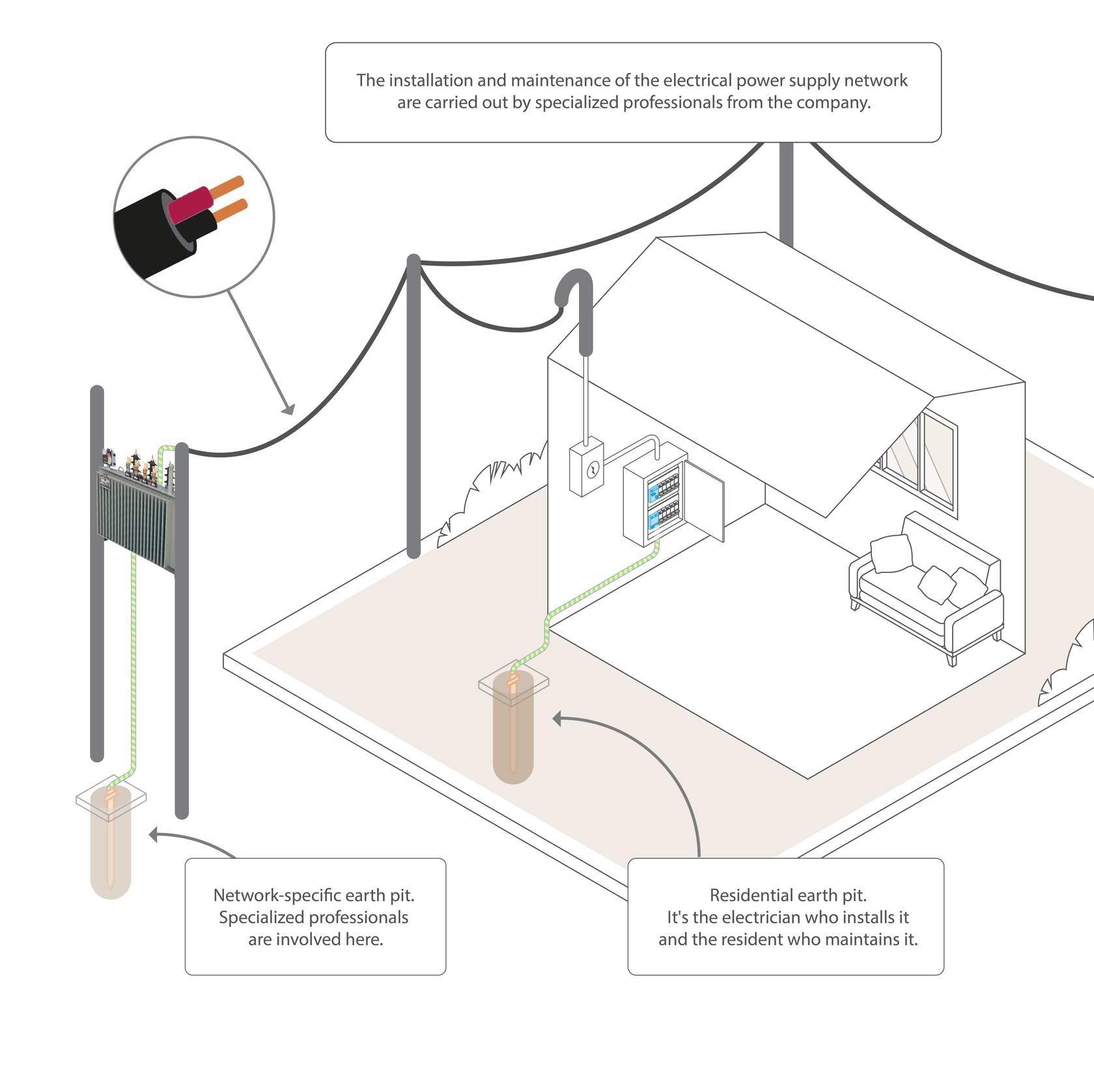
The Person Who Have the Duty of Grounding System
- Electrician = in building area
- Professional Electrical Engineer (from the Grid Network services company) = in the nearest Transformer
Symbol of Grounding Systems

Symbol for Each Configuration

Three phase

Single phase
Standard of Grounding System
- Common standards = IEC 60364 = Electrical Installations in Buildings,
- Earthing System = IS 3043:2018 Section 14 = Code of Practice for Earthing
- Risky Area in a Bathroom = IS 732:1989 Section 5.1.6.1= Code of Practice for Electrical Wiring Installations
- How do The System = SP30:2011 Section 14 = Earthing
- Earthing System [Earthing Pits, Methods] = IS 732:1989 Section 8 = Code of Practice for Electrical Wiring Instllations
- Earth pit procedure (Connection, Product, Process, Measurement) = IS 3043:2018 = Code of Practice for Earthing


Excellent work
Good one
Easy